發布日期:2022-05-20 點擊率:51
步驟1:操作
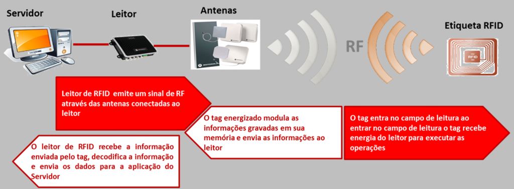
RFID系統基本上由帶有解碼器的收發器,天線和應答器組成。以及它如何運作?這些卡中有一個卷軸。當您從閱讀器接近它們時,它們會通過連接到閱讀器的天線發出無線電信號。帶電標簽(即卡)對存儲在其內存中的信息進行調制,然后將該數據發送到讀取器。然后,該卡進入讀取區域并從讀取器接收電源以執行操作。 RFID閱讀器接收標簽發送的信息,將數據解碼并將其發送到服務器應用程序。
步驟2:內存

《如前所述,這種芯片內部有1k的內存。并且,EEPROM存儲器的組織方式如下:4個塊的16個扇區。每個塊包含16個字節。請記住,在源代碼中,您僅引用塊號。
步驟3:電路

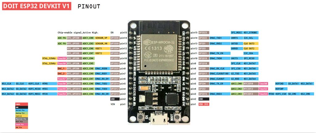
在此圖中,帶有RFID芯片的鑰匙扣,除了組裝件,我們還有傳統的卡。以及該電路如何工作?嗯,在互聯網上,您會發現RFID-RC522模塊非常適合Arduino使用,但問題是該Arduino(無論是Mega,Nano),無論型號如何,都無法通信,例如WiFi網絡,以太網,彼此之間。所以我們在這里使用ESP32。它已經具有藍牙,RF,即易于通信。那么我在這里指出,幾乎所有與Arduino兼容的東西都可以在ESP32上使用。
返回電路,當在對卡或芯片進行分析時,綠色LED亮起時,這意味著標識已完成,訪問被釋放。紅色LED點亮時,表明數據尚未通過驗證。
步驟4:WiFi NodeMCU-32S ESP-WROOM-32
步驟5:RFID-RC522
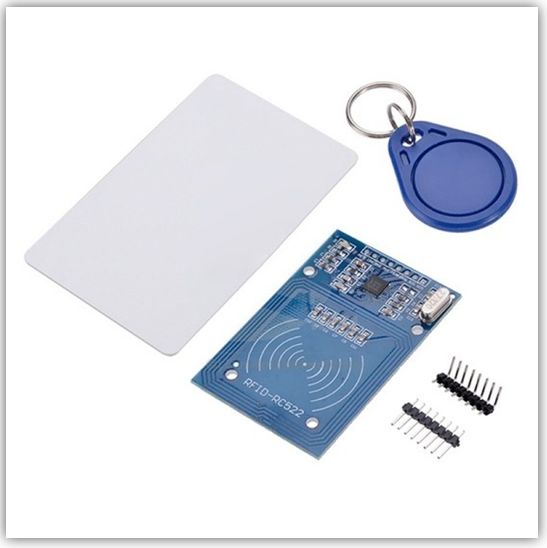

在這里,我們獲得了卡和鑰匙圈以及RFID天線的圖像。一個重要的細節是它的接口是SPI。
第6步:組裝

在我們的組裝中,我們的ESP32由USB,并以Arduino IDE的串行連接,有兩個LED指示讀取是否成功,還有RFID讀取器RC522。我們有帶芯片和卡的鑰匙圈。
將鑰匙圈放在播放器上會顯示0表示讀取數據,1表示記錄數據。我們以一個示例為例,該示例顯示讀取芯片或卡后,如果綠色指示燈點亮,則讀取器會識別出該數字。如果指示燈為紅色,則表示發生了某種類型的錯誤,并且未執行身份驗證。
在示例中,我仍然展示了如何將數據寫入標簽,下面將對此進行說明。
第7步:庫

添加以下庫“ MFRC522”。
只需訪問“草圖” 》》包括庫》》管理庫。..”
步驟8:源代碼

我們的程序將按以下方式工作:啟動后,程序將等待卡或標簽被識別。之后,將出現一個菜單,供用戶在閱讀或記錄內容之間進行選擇。然后將執行該操作。
步驟9:設置
在這一部分中,我們處理庫的包含并定義緩沖區和塊數據大小。我們創建對象并初始化引腳,以及串行,SPI通信,LED和天線服務。我已經開始在串行監視器上包含消息了。
#include //library responsible for communicating with the module RFID-RC522
#include //library responsible for communicating of SPI bus
#define SS_PIN 21
#define RST_PIN 22
#define SIZE_BUFFER 18
#define MAX_SIZE_BLOCK 16
#define greenPin 12
#define redPin 32
//used in authentication
MFRC522::MIFARE_Key key;
//authentication return status code
MFRC522::StatusCode status;
// Defined pins to module RC522
MFRC522 mfrc522(SS_PIN, RST_PIN);
void setup()
{
Serial.begin(9600);
SPI.begin(); // Init SPI bus
pinMode(greenPin, OUTPUT);
pinMode(redPin, OUTPUT);
// Init MFRC522
mfrc522.PCD_Init();
Serial.println(“Approach your reader card.。.”);
Serial.println();
步驟10:循環
在循環中,我們等待卡方法并選擇相同的方法。在菜單中,我們提供了讀取或寫入數據的選項。當設備應從活動狀態變為停止狀態時,我們對此部分進行了指示。我們必須使用這種方法來啟用新的讀數。
void loop()
{
// Aguarda a aproximacao do cartao
//waiting the card approach
if ( ! mfrc522.PICC_IsNewCardPresent())
{
return;
}
// Select a card
if ( ! mfrc522.PICC_ReadCardSerial())
{
return;
}
// Dump debug info about the card; PICC_HaltA() is automatically called
// mfrc522.PICC_DumpToSerial(&(mfrc522.uid));
//call menu function and retrieve the desired option
int op = menu();
if(op == 0)
readingData();
else if(op == 1)
writingData();
else {
Serial.println(F(“Incorrect Option!”));
return;
}
//instructs the PICC when in the ACTIVE state to go to a “STOP” state
mfrc522.PICC_HaltA();
// “stop” the encryption of the PCD, it must be called after communication with authentication, otherwise new communications can not be initiated
mfrc522.PCD_StopCrypto1();
}
步驟11:閱讀
在這一部分中,我們將閱讀卡/標簽的數據。我們必須準備所有鍵,處理緩沖區的大小,并對要操作的塊進行身份驗證。最后,我們設置讀取數據的打印方式。
//reads data from card/tag
void readingData()
{
//prints the technical details of the card/tag
mfrc522.PICC_DumpDetailsToSerial(&(mfrc522.uid));
//prepare the key - all keys are set to FFFFFFFFFFFFh
for (byte i = 0; i 《 6; i++) key.keyByte[i] = 0xFF;
//buffer for read data
byte buffer[SIZE_BUFFER] = {0};
//the block to operate
byte block = 1;
byte size = SIZE_BUFFER;
//authenticates the block to operate
status = mfrc522.PCD_Authenticate(MFRC522::PICC_CMD_MF_AUTH_KEY_A, block, &key, &(mfrc522.uid)); //line 834 of MFRC522.cpp file
if (status != MFRC522::STATUS_OK) {
Serial.print(F(“Authentication failed: ”));
Serial.println(mfrc522.GetStatusCodeName(status));
digitalWrite(redPin, HIGH);
delay(1000);
digitalWrite(redPin, LOW);
return;
}
//read data from block
status = mfrc522.MIFARE_Read(block, buffer, &size);
if (status != MFRC522::STATUS_OK) {
Serial.print(F(“Reading failed: ”));
Serial.println(mfrc522.GetStatusCodeName(status));
digitalWrite(redPin, HIGH);
delay(1000);
digitalWrite(redPin, LOW);
return;
}
else{
digitalWrite(greenPin, HIGH);
delay(1000);
digitalWrite(greenPin, LOW);
}
Serial.print(F(“ Data from block [”));
Serial.print(block);Serial.print(F(“]: ”));
//prints read data
for (uint8_t i = 0; i 《 MAX_SIZE_BLOCK; i++)
{
Serial.write(buffer[i]);
}
Serial.println(“ ”);
}
步驟12:記錄
要將數據寫入卡/標簽,我們必須遵循一些步驟。從選擇記錄選項的那一刻起,我們有30秒的時間通過串行進行數據輸入。用“#”字符輸入要寫入的數據并準備密鑰。您將需要清除緩沖區并寫入塊1,因為在塊0中,我們已經保存了卡號,該卡號已經在工廠中了。因此,我們不會觸摸塊0。
我們處理數據的大小,并插入一個用于身份驗證的命令并啟用安全通信。如果未認證的數據,我們還會將錯誤消息與讀數的一部分相等,以進行顯示。我們將數據記錄在適當的塊中。
//prints thecnical details from of the card/tag
mfrc522.PICC_DumpDetailsToSerial(&(mfrc522.uid));
// waits 30 seconds dor data entry via Serial
Serial.setTimeout(30000L) ;
Serial.println(F(“Enter the data to be written with the ‘#’ character at the end [maximum of 16 characters]:”));
//prepare the key - all keys are set to FFFFFFFFFFFFh
for (byte i = 0; i 《 6; i++) key.keyByte[i] = 0xFF;
//buffer para armazenamento dos dados que iremos gravar
//buffer for storing data to write
byte buffer[MAX_SIZE_BLOCK] = “”;
byte block; //the block to operate
byte dataSize; //size of data (bytes)
//recover on buffer the data from Serial
//all characters before chacactere ‘#’
dataSize = Serial.readBytesUntil(‘#’, (char*)buffer, MAX_SIZE_BLOCK);
//void positions that are left in the buffer will be filled with whitespace
for(byte i=dataSize; i 《 MAX_SIZE_BLOCK; i++)
{
buffer[i] = ‘ ’;
}
block = 1; //the block to operate
String str = (char*)buffer; //transforms the buffer data in String
Serial.println(str);
//authenticates the block to operate
//Authenticate is a command to hability a secure communication
status = mfrc522.PCD_Authenticate(MFRC522::PICC_CMD_MF_AUTH_KEY_A,
block, &key, &(mfrc522.uid));
if (status != MFRC522::STATUS_OK) {
Serial.print(F(“PCD_Authenticate() failed: ”));
Serial.println(mfrc522.GetStatusCodeName(status));
digitalWrite(redPin, HIGH);
delay(1000);
digitalWrite(redPin, LOW);
return;
}
//else Serial.println(F(“PCD_Authenticate() success: ”));
//Writes in the block
status = mfrc522.MIFARE_Write(block, buffer, MAX_SIZE_BLOCK);
if (status != MFRC522::STATUS_OK) {
Serial.print(F(“MIFARE_Write() failed: ”));
Serial.println(mfrc522.GetStatusCodeName(status));
digitalWrite(redPin, HIGH);
delay(1000);
digitalWrite(redPin, LOW);
return;
}
else{
Serial.println(F(“MIFARE_Write() success: ”));
digitalWrite(greenPin, HIGH);
delay(1000);
digitalWrite(greenPin, LOW);
}
}
步驟13:菜單
在這里編寫菜單。監視器顯示所有選項,并等待發送數據。選擇一個選項后,它將從讀取的值中刪除48,該值在Ascii表中為0。該表是舊的,不在PC上使用,但是在Arduino和微控制器上,您將不得不處理它。如果您不知道,請在互聯網上搜索一下它是什么。
//menu to operation choice
int menu()
{
Serial.println(F(“ Choose an option:”));
Serial.println(F(“0 - Reading data”));
Serial.println(F(“1 - Writing data ”));
//waits while the user does not start data
while(!Serial.available()){};
//retrieves the chosen option
int op = (int)Serial.read();
//remove all characters after option (as per example)
while(Serial.available()) {
if(Serial.read() == ‘ ’) break;
Serial.read();
}
return (op-48);//subtract 48 from read value, 48 is the zero from ascii table
}
下一篇: PLC、DCS、FCS三大控
上一篇: 怎樣去搭建和運行RFID